
Wire EDM melts the workpiece with the discharge current between the molybdenum wire and the conductive workpiece. The high-frequency power supply generates the pulse voltage that drives that current, so setting the electrical parameters correctly is the basis of machining quality.
1. General Tuning Principles
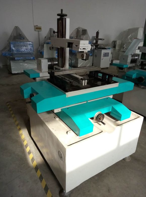
For a 50mm workpiece with 0.16mm molybdenum wire, a typical start is: voltage on position 2, pulse amplitude on 1+2+2, pulse width on position 3, pulse interval in the middle — a stable cutting current of about 2.0A.
- Set feed speed last: after choosing voltage, amplitude, pulse width and interval, measure the short-circuit current, then start cutting and adjust the frequency drive and tracking knob so the machining current reaches 70–75% of that value.
- Change settings gradually: switch states at spool reversal or with the high frequency off, never in large single steps, to prevent wire breakage.
- New wire, lower current: on a fresh wire, start at one-third to two-thirds of the normal current and return to full current after about ten minutes; this extends wire life.
2. The Four Electrical Parameters
Working voltage (70–110V, three ranges). Below 50mm: 70V (position 1); 50–150mm: 90V (position 2); above 150mm: 110V (position 3).
Working current (pulse amplitude switches). Five switches combine into 12 power levels. More stages on (more power transistors) means higher current and speed but worse roughness at the same pulse width. By height: below 50mm use 1–5; 50–150mm use 3–9; 150–300mm use 6–11.
Pulse width (8–80μs, five positions). A wider pulse means longer discharge time and larger single-pulse energy — stable, efficient cutting but a rougher finish; a narrower pulse is the reverse. By height: below 15mm use 1–5; 15–50mm use 2–5; above 50mm use 3–5.
Pulse interval (fine adjustment). Turning clockwise increases the interval, counterclockwise decreases it. For thicker workpieces a larger interval aids flushing and reduces debris, preventing breakage. Check: with stable high-frequency current, turn the knob — a current drop means the interval has increased.
3. Common High-Frequency Faults
Fault: current adjustment still has no effect after replacing the power transistors. The problem may not be the transistors — a parallel resistor with the same failure mode shows the same symptom. HS-WEDM oscillator boards are inexpensive and usually replaced whole; MS-WEDM boards cost more and can be returned for repair. Basic circuit diagnosis saves downtime.
Fault: no high frequency at startup (threading) but a tingling sensation. Usually from the breakage protection, with very low current (below 24V). Turn off the mains before threading; do not disable breakage protection — it protects both machine and wire. If voltage remains after disabling it, the machine may have an electrical leak — contact the manufacturer.
4. Intelligent Pulse Power Supplies
Modern MS-WEDM machines increasingly use intelligent pulse power modules — a DC supply, smart oscillator, pre-amplifier, power stage and sampling circuit — with pulse energy controlled by programmable software and real-time servo tracking. Typical specifications: three-phase 380V/50Hz input, peak pulse voltage up to 105V DC, maximum current 10A, maximum thickness 800mm, and Ra ≤1.0μm on multi-pass cuts of 20mm hardened Cr12 steel.
Summary. Tune parameters by workpiece height, set feed from the short-circuit current, and change settings gradually to prevent breakage. When a fault appears, decide whether the transistors or the parallel resistors are at fault, then replace or repair accordingly.
Need more information? — we reply within 24 hours. Contact our sales team