
Workpiece alignment directly affects part quality, productivity and machine life. The goal is to make one workpiece surface parallel or perpendicular to a machine axis so the cut matches the drawing.
1. Common Alignment Methods
Dial indicator method
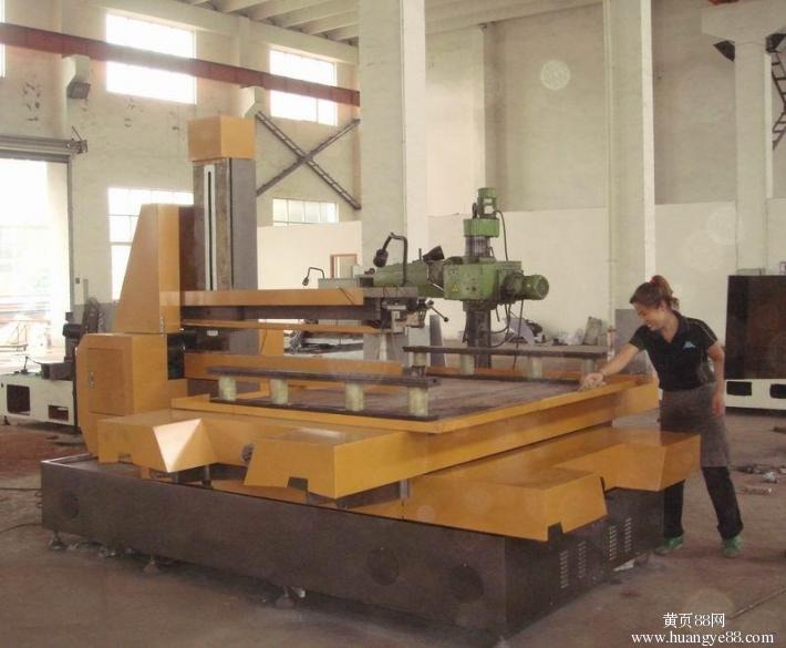
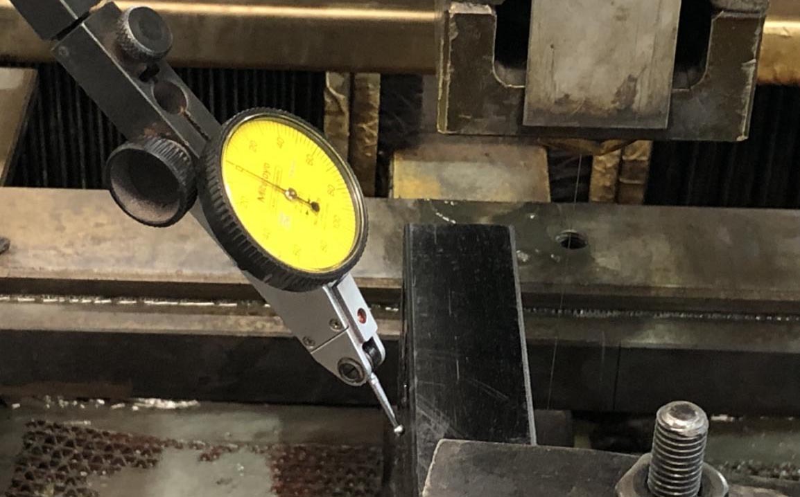
Most wire EDM machines (cantilever, C-frame and E-frame types) have two bridge plates parallel to and level with the X and Y axes. Position the workpiece with preliminary clamping, mount a dial indicator on a magnetic base against the reference face, then move the table back and forth and adjust the workpiece until needle deflection stays within tolerance. Tighten the clamps.
Scribed line method
For thin multi-layer sheet-metal parts with uneven edges, bring the stationary molybdenum wire progressively toward a scribed line. Suitable when positional accuracy is moderate and an allowance exists.
Paper template method
The most common approach. When a thin multi-layer part needs both external contours and internal holes, print the finished part at 1:1, paste it on the workpiece, and use it to place the pre-drilled threading holes. Punching stays on target and alignment is simple.
Spark discharge method
The discharge gap between wire and workpiece is roughly 0.01–0.02 mm. Advance the wire until a spark appears; accuracy is about 0.02–0.05 mm, limited by wire vibration and spark force. If a threading hole carries non-conductive oxide after heat treatment, file it off or re-reference with a square-edge notch.
Tooling hole method
When a plate has accurate tooling holes, matching holes in the bridge-plate fixture allow quick pin-based positioning.
Multimeter resistance method (highest accuracy)
With the wire stationary, connect one meter lead to the wire and one to the workpiece, advance until the meter conducts, then retreat in 0.001 mm steps until open circuit; repeat to confirm. Theoretical accuracy reaches 0.001 mm.
2. Dialing In a Clamped Workpiece
Indicator gauges are graded by division: 0.01 mm (dial indicator), 0.005 mm, 0.002 mm and 0.001 mm; at 0.001 mm, one division is 1 µm.
- Fix the gauge base (strong magnet) to a stationary part such as the wire guide arm.
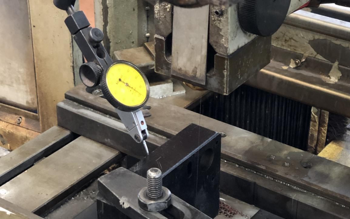
- Bring the needle into contact with the workpiece via the X/Y axes.
- Zero it near the dial center so scale remains on both sides.
- Move the workpiece along the parallel axis: rising readings mean the part tilts closer on that side, falling readings mean farther.
- Tap it lightly with a copper bar to square it to the axis.
- When deflection meets tolerance, clamping is complete.
3. Finding Center Without Precise Center
For one-off parts, clamp one edge, square the top face, split the Y axis at the high point, and use half of the X-axis touch value to find center. If high concentricity is not required, measure the circle diameter, split the X axis, and push from the vertex to center. For batch work, use a clamping set and square block before finding the outline, or make a dedicated vertical vise.
Summary: Alignment is a fundamental wire EDM skill; mastering the dial indicator and multimeter resistance methods covers most production work.
Need more information? — we reply within 24 hours. Contact our sales team