
CAD drafting and programming are the foundation of wire EDM work. Understanding G codes, path layout and image conversion is key to quality and efficiency.
1. Common G Codes (MS-WEDM / HS-WEDM)
- G90 absolute coordinates; G91 incremental (fixed for 3B).
- G92 defines the program datum (3B start point).
- G00 rapid positioning; G01 linear cut (L1–L4); G02 clockwise arc (SR); G03 counterclockwise arc (NR).
- G41 left compensation; G42 right compensation; G40 cancel compensation (lead-in needs none).
- M00 program stop; M02 end of program.
- A taper code (A3 = 3°); T tool change for skim cuts (T2 = skim with tool 2).
Line format: G01 Xx Yy. Arc format: G02/G03 Xx Yy Ii Jj — xy is the end point, ij the arc center relative to the start.
2. Tool Path Layout Principles
A well-planned path improves accuracy and reduces distortion:
- Cut first where machining is easy and affects the part least.
- Keep the path a safe distance from the workpiece face.
- Schedule un-machined sides and the clamping end last.
- Prefer a threading hole over entering from the face on high-accuracy parts, and use a second pass on large parts.
- Cut two parts from one blank via separate threading holes.
3. Converting an Image Into a Cutting Drawing
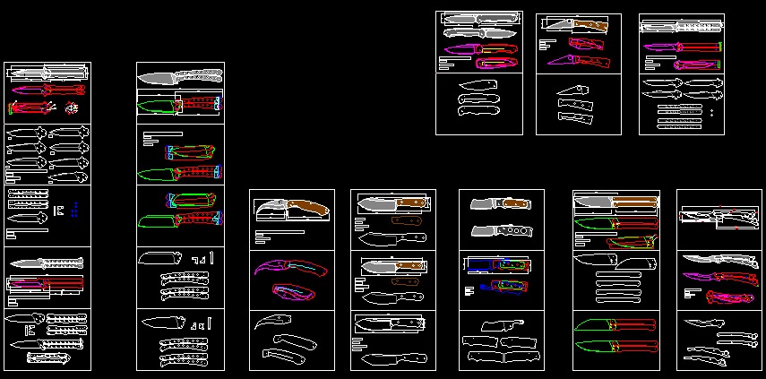
In CAD: insert the image, trace the outline with lines and arcs, delete the image, close all contours and fix areas too narrow to cut. Save as DXF 2000, test the path, then run.
In CAXA: use vectorization and select the JPG directly, or convert it to BMP and import via bitmap vectorization. Repair the result before programming.
4. Programming Tips
Clean entry: arc in and out on external profiles; enter holes from a sharp corner or open closed contours; stagger entry points on skim passes; enter slanted profiles 3–5° on a tangent.
Distortion control: support at solid points after roughing; add multiple supports for long punches, inserts and thin-wall holes; use a threading hole for large or long outlines.
Consistent dimensions on thick parts: raise wire speed and slightly increase tension; skim the first pass more times; reduce voltage 5–10 V on concave external profiles and raise it 5–10 V on concave holes.
Other tips: cut holes under 2 mm chip-free (unless tapered); rough all holes first, then grind flat, then finish-skim for precision dies; keep the head low on MS-WEDM skims; keep lead screw oil out of the dielectric tank; never mix oil-based into water-based dielectric; a sapphire flushing nozzle improves HS-WEDM finish.
5. Sprocket Drawing in AutoCAD
Sprocket drafting needs: d1 roller diameter, p pitch, z teeth, a groove angle, d pitch-circle diameter, root/face arc radii, tip/root circle diameters and chord tooth height. For a 12-tooth sprocket at 50.8 pitch: d = p ÷ sin(180°÷z) ≈ 196.28; use a mid-range root arc radius (~14.44), a 132.5° groove angle, minimum face arc radius, tip circle 217, then trim, mirror and array 12 teeth.
Summary: G code, path layout and image conversion are the basics of wire EDM programming; the tips above speed up drafting and improve quality.
Need more information? — we reply within 24 hours. Contact our sales team