
Wire EDM shapes a workpiece by spark discharge through a molybdenum wire electrode. Because the wire has a finite radius (typically 0.16mm or 0.18mm) and the discharge leaves a gap, the wire path must be shifted a normal distance from the workpiece contour — the offset (compensation). Get it wrong and the part misses the drawing.
1. The Basic Offset Formula
Offset = wire radius + discharge gap (+ other influence factors)
Example: a 0.18mm wire with a 0.01mm discharge gap gives a basic offset of 0.18/2 + 0.01 = 0.10mm.
The discharge gap is looked up from standard reference tables according to workpiece thickness, wire radius and current. For high-precision work, secondary factors such as wire vibration should also be included.
2. Offset Direction: Internal Holes vs. External Profiles
Internal holes and external profiles use opposite compensation signs:
- Internal hole, cut tight: offset = (wire radius + discharge gap) + extra clearance wanted
- Internal hole, enlarge clearance: offset = (wire radius + discharge gap) − clearance required
- Out-of-range (negative) compensation is applied on the outside of the path
- External profiles: signs reversed — adding clearance means adding, reducing means subtracting, and out-of-range compensation goes inside the contour
3. Worked Examples for Die Machining
Given: wire radius 0.06mm, one-side gap 0.01mm, fit clearance 0.015mm; backing plate 0.01mm smaller, stripper plate 0.02mm larger than the punch.
Piercing die (part size governed by the punch; fit clearance taken off the die):
- Punch: f = 0.06 + 0.01 = 0.07
- Die: f = 0.06 + 0.01 − 0.015 = 0.055
- Backing plate: f = 0.06 + 0.01 + 0.01 = 0.08
- Stripper plate: f = 0.06 + 0.01 − 0.02 = 0.05
Blanking die (part size governed by the die; fit clearance taken off the punch):
- Die: f = 0.06 + 0.01 = 0.07
- Punch: f = 0.06 + 0.01 − 0.015 = 0.055
- Backing plate: f = 0.06 + 0.01 + 0.01 + 0.015 = 0.095
- Stripper plate: f = 0.06 + 0.01 + 0.015 − 0.02 = 0.065
Note: punches and mold ejector pins differ — a 5mm punch is a standard 5mm, but an ejector pin for the same hole is 4.975mm. The same hole cut with different compensation is a different part.
4. Offset Settings for Multi-Pass Cutting
Medium-speed wire EDM (MS-WEDM) commonly uses multi-pass cutting. Principles for setting each pass:
- The second pass decides final size; later skim passes barely affect it
- The final skim pass controls surface finish
- Each earlier pass leaves an allowance of wire radius + discharge gap + one-side skim allowance; the last pass takes none
- If finish improves but size accuracy worsens, re-check the allowances — thick parts and weak regimes are more sensitive to how allowances are distributed
- For critical or tall parts, verify offset data for every pass; do not rely on the manual alone
5. Manual Skim-Cut Compensation on HS-WEDM
High-speed wire EDM (HS-WEDM) has no automatic skim-cut function, so compensation is calculated by hand:
- Offsets depend mainly on workpiece thickness and vary with material (commonly 0.02–0.06mm)
- Parts over 50mm thick commonly use offset pairs of 0.055mm and 0.015mm
- Wrong first- and second-pass offsets stall the skim passes and produce a barrel-shaped part
- Trial-cut tight-tolerance parts first; measure the wire diameter regularly after prolonged use and recalculate from the actual diameter
- For parts that fit into an assembly, allow for tolerances, use a small R at small corners, and distinguish internal from external R
6. Broken Compensation Paths and Reverse Compensation
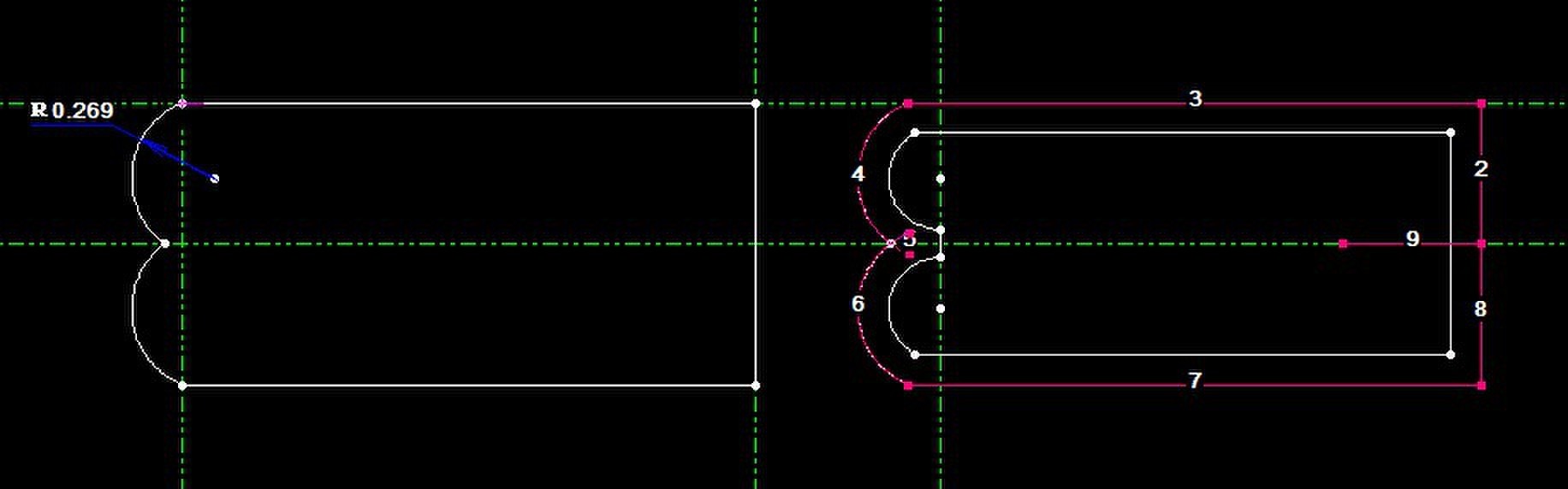
When two small arcs meet in a cavity and the software reports “path breaks after compensation”:
- Offset the original geometry inward by one compensation value
- Start an equidistant offset from the arc junction and draw a 90° auxiliary line from either arc center
- Extend both arcs to the auxiliary line and connect the intersections
- Apply reverse (outward) compensation to generate the correct program
Mastering the offset formula, the inside/outside sign convention and the die examples — plus “measure the wire often, trial-cut tight parts first” — is the foundation of accurate wire EDM programming.
Need more information? — we reply within 24 hours. Contact our sales team