
Punches, carbide blanks and gears place higher demands on wire EDM than ordinary parts. Knowing the specific requirements of each is the first step toward stable quality and good efficiency.
1. Punch Machining Essentials (Carbide Toothed Punch as an Example)
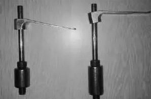
Stress control. Residual stress in the blank and discharge heat both cause deformation. Drill a threading hole first and cut in a closed-loop pattern to avoid open-cut distortion. When blank dimensions rule out a closed cut, plan the cutting direction carefully in the program.
Cutting path design. The path should keep the punch in a fixed coordinate system relative to the fixture. With the blank clamped on the left, cut the punch counterclockwise from the left side so the part stays near the clamped zone with good rigidity for most of the cut. Leave the cut that separates the finished part from the clamp until the end of the program, with the pause point near the clamped end.
Carbide process treatment. For regular-shaped punches, leave a connecting tab at a flat location and trim it with a single final cut, then hand-finish flat; this reduces cost. Because carbide is hard, narrow and prone to deformation, adjust the process so dimensional accuracy is met without hand finishing. Use four cuts for the contour and tab with identical parameters and offset: the first cut runs at a larger offset of 0.5–0.8 mm to release internal stress, followed by three finishing cuts.
Recommended parameters. Pre-drill a 1.0–1.5 mm threading hole with a 5–10 mm lead-in. Keep the width between the punch contour and blank edge at least one-fifth of the blank thickness, and place the pause point (3–4 mm wide) near the blank’s center of gravity. Rough cut first at 0.5–0.8 mm offset, then finish with three cuts. After cutting, blow the part dry, clean with alcohol and air-dry. Bond a flattened ~1.5 mm metal shim onto the blank with fast-setting cyanoacrylate glue, then cut the connecting tab at the original offset. Do not let glue reach the tab or the flushing nozzle, or conductivity will be lost.
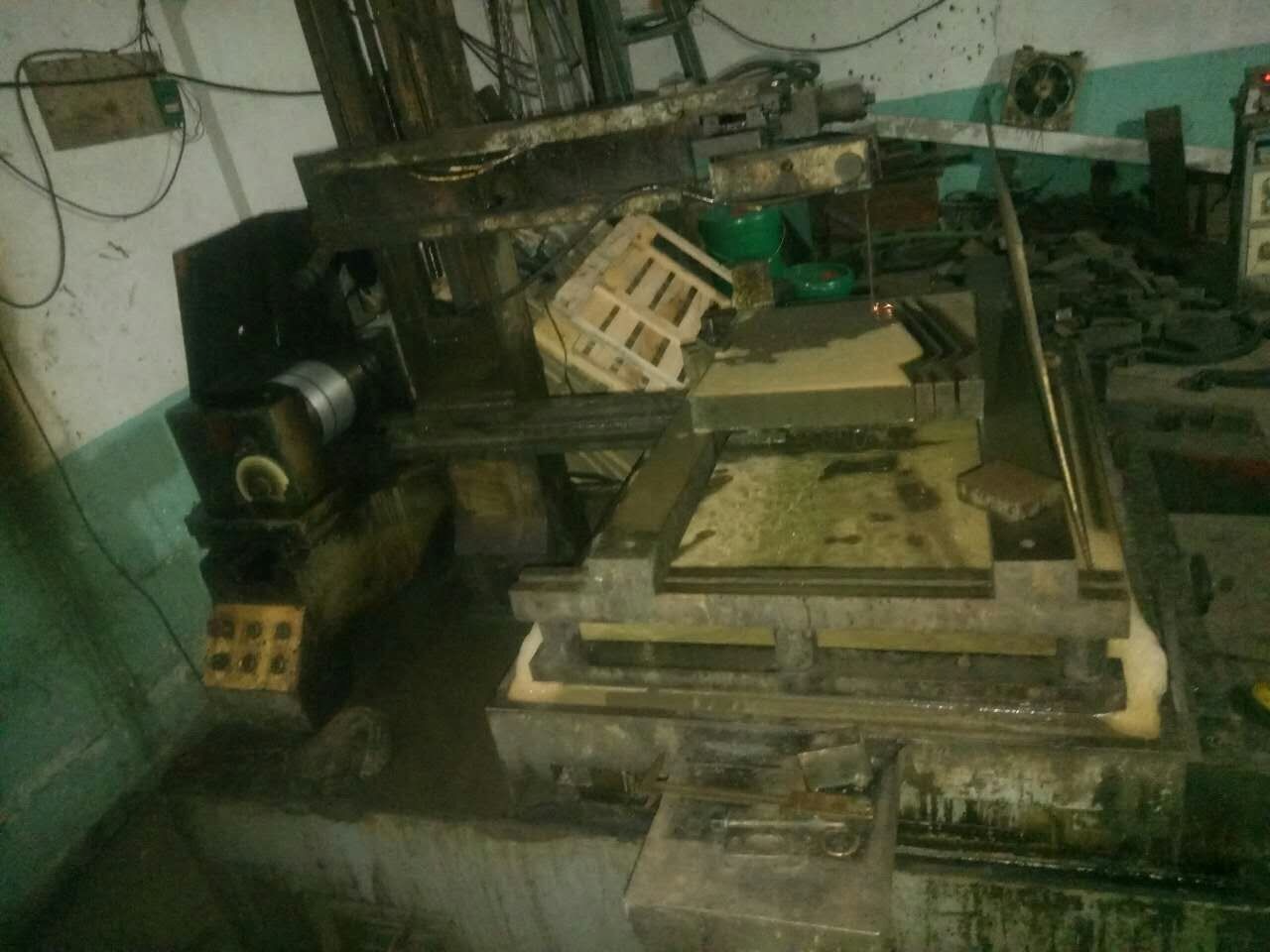
2. Preventing Carbide Cracking and Wire Breakage
Against cracking. When sintering large carbide blocks, slow down heating and cooling and extend high-temperature holding time as far as allowed. Let carbide naturally age for 1–2 months (or cold-treat at 0–10 °C) before machining, and rough-grind first, then wait a few days before cutting. The goal is to release internal stress as evenly as possible before machining.
Against wire breakage. Replace the guide wheels and conductive blocks. Replace the working fluid and raise the mix concentration, or use a water-based dielectric with strong flushing performance, since carbide produces a lot of erosion debris that quickly degrades flushing. Keep machine parameters stable: do not over-tighten the molybdenum wire, keep the wire guide arm low and speed moderate, keep the variable-frequency tracking steady, hold current at 2.5 A (no more than 3 A) and widen the pulse interval relative to pulse width.
3. Gear Cutting Basics
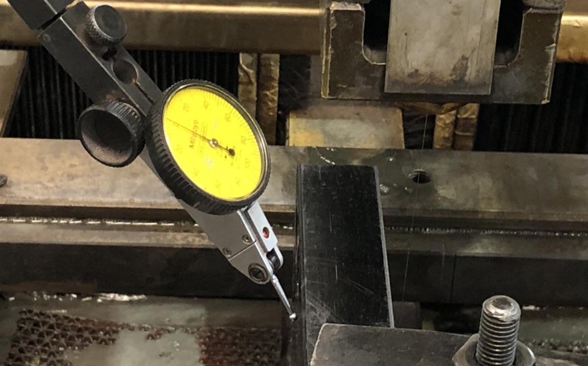
Cutting gears with wire EDM is straightforward: the software includes gear routines that generate the profile automatically once module and tooth data are entered. External gears are usually hobbing jobs, while internal gears are cut by wire EDM or gear shaping. The module is the sizing standard, and knowing the module and tooth count defines the overall dimensions of a spur gear.
Summary. Special-workpiece machining comes down to stress control plus parameter tuning. Punches demand careful cutting paths and offset allocation, carbide requires aging treatment and breakage-resistant parameters, and gears make the most of automatic program generation. Follow these points and special parts can be cut reliably.
Need more information? — we reply within 24 hours. Contact our sales team