
Calibrating the verticality of the molybdenum wire before wire EDM cutting ensures that the workpiece reference face and the cutting face meet at 90 degrees. Without calibration, the cut face is tilted and the workpiece is scrapped.
1. Calibration Principle and Tools
“Wire vertical” refers to the perpendicularity of the wire to the X/Y plane, which directly affects machining accuracy. Common tools include dumbbell-shaped, cylindrical, L-shaped and square hexahedron gauges, plus conductive-contact gauges with a meter readout; any works well if accurate and used correctly. The square hexahedron is easiest to self-check: place it flat on the bed and measure three adjacent faces with the X and Y coordinates.
2. Spark-Based Alignment (Most Intuitive)
Most alignment relies on discharge sparks — the most direct and trustworthy method.
- Confirm the top face of the gauge is parallel to the X/Y plane before use.
- Align with no fluid and low current, typically using only one output stage, or the gauge erodes quickly.
- With sparks uniform over a face of at least 50 mm, accuracy is usually within 0.01 mm.
- Adjust alternately in both horizontal directions and repeat twice.
3. Calibration Steps on MS-WEDM
- Threading check: after threading, confirm the wire stays on the guide wheels, then tension it.
- Position the guide wheels: in the C-frame design, the lower guide wheel shifts sideways and the upper guide wheel front-to-back. Do an initial alignment when fixing the wheels to bring the wire perpendicular to the worktable reference plane (usually preset by the manufacturer).
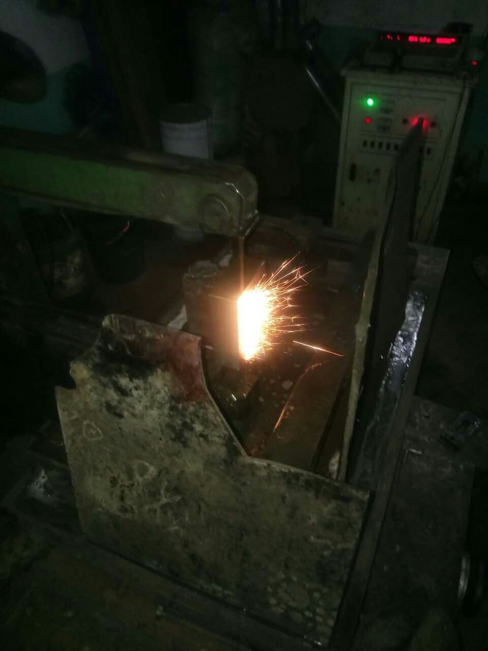
- Spark alignment: enable wire-contact mode and touch the gauge; retract immediately on contact to avoid burning the workpiece. Adjust the taper mechanism until contact is uniform in both directions.
- Trial cut confirmation: place the gauge on the workpiece reference face or touch it directly. Align the workpiece during clamping, complete the dial indicator check, then fine-tune the taper mechanism.
4. Calibration Steps on HS-WEDM
- After threading, confirm the wire stays on the guide wheels, then tension it.
- Align the workpiece during clamping and complete the dial indicator check before wire contact; always enable wire-contact mode when touching the wire.
5. Adjustment Mechanisms
- Machines without taper: fix the lower guide wheel and adjust the upper guide wheel via the two end caps; the frame’s longitudinal position is set with the frame adjusting screws.
- Machines with taper: the UV travel can be used, but its center must not shift once the wire is calibrated, or taper function is affected; maximum deviation ±1 mm.
6. Precautions
- Always enable wire-contact mode when touching the wire; calibrate verticality before fitting the sapphire nozzles during installation.
- Flatness of the workpiece top face matters: calibrating an uneven workpiece produces a tapered, sloped cut — small, but unacceptable for high-precision work, so dial the workpiece in with an indicator first.
- There is no shortcut — sparks at the top mean turn one way, sparks at the bottom mean turn the other.
Dial indicator supplement: for batch rectangular workpieces, dial in against the workpiece holder first. Press the indicator tip against the long side, move the table and watch the needle, tap the workpiece with a copper rod until the needle holds steady, then clamp with a pressure plate. Dirt under the holder can tilt the beam, so re-check before high-precision work.
Need more information? — we reply within 24 hours. Contact our sales team